Definition

Galvanometer as a voltmeter

To convert a galvanometer into a voltmeter it must be connected in parallel with the circuit across which the voltage is to be calculated. Moreover a negligible amount of current should be drawn from it such that it doesn't disrupt the original set up by a large amount and well below one per cent. To ensure this, a large resistance is connected in series with the galvanometer.
Definition
Galvanometer as a voltmeter

The galvanometer can also be used as a voltmeter to measure the voltage across a given section of the circuit. For this it must be connected in parallel with that section of the circuit. Further, it must draw a very small current, otherwise the voltage measurement will disturb the original set up by an amount which is very large. Usually we like to keep the disturbance due to the measuring device below one per cent. To ensure this, a large resistance R is connected in series with the galvanometer.
Definition
Describe the working of an ammeter

As shown in block diagram, in a typical Digital multimeter the input signal i.e ac or dc voltage, current, resistance, temperature or any other parameter is converted to dc voltage within the range of the Analog to Digital Convertor. The analog to digital converter then converts the pre-scaled dc voltage into its equivalent digital numbers which will be displayed on the display unit. Sometimes, digital controller block is implemented with a microcontroller or a microprocessor manages the flow of information within the instrument. This block will coordinate all the internal functions as well as transferring information to external devices such as printers or personnel computer.
Definition
Wheatstone bridge

The wheatstone bridge is an arrangement of four resistors . Across one point of diagonally opposite points, a source is connected. This is called the battery arm. Between the other two vertices, a galvanometer is connected. This is called the galvanometer arm.
At null deflection point,
At null deflection point,
Definition
Kelvin's method to determine resistance

A Kelvin bridge is a modified wheatstone bridge used to measure unknown electrical resistors below . It is specifically designed to measure resistors that are constructed as four terminal resistors.
In the attached diagram of Kelvin's Bridge, C is the unknown resistance.
Solving above equations give
In the attached diagram of Kelvin's Bridge, C is the unknown resistance.
Solving above equations give
Example
Solving circuit of Wheatstone bridge
Example:
In a Wheatstone's bridge, three resistances P,Q and R are connected in three arms and the fourth arm is formed by two resistances and connected in parallel. Find the condition for the bridge to be balanced.
Solution:The condition for Wheatstone bridge is:
in parallel]
In a Wheatstone's bridge, three resistances P,Q and R are connected in three arms and the fourth arm is formed by two resistances and connected in parallel. Find the condition for the bridge to be balanced.
Solution:The condition for Wheatstone bridge is:
in parallel]
Definition
Potentiometer

Potentiometer is a device used to compare the emfs of two cells.(or) to find the emf of a cell (or) to find the internal resistance of a cell (or) to measure potential difference.
Construction: A potentiometer consists of uniform wire of length 10m arranged between A and B as 10 wires each of length 1m on a wooden board. The wire has specific resistance and low temperature coefficient of resistance (constantan or manganine). A meter scale is arranged parallel to the wires to measure the balancing length. The resistance of the total wire of the potentiometer is about 5. A Jockey J can be moved on the wire. The balancing length is measured from the end which is connected to the positive terminal of the battery.
Principle:In null deflection position,
Unknown potential difference = Known potential difference.
When steady current passes through the uniform wire of the potentiometer, the potential difference across any part of the wire is directly proportional to the length of the wire.
Definition
Comparision of emfs using a potentiometer
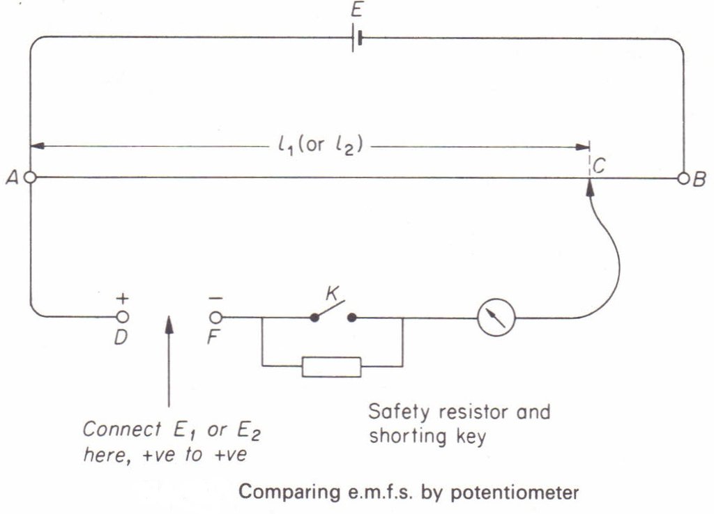
Comparison of Emfs:
The driving circuit of a potentiometer is set up with a strong battery so that the potential difference across AB is larger than the emf of either battery. One of the batteries is connected between the positive end A and the galvanometer. The jockey is adjusted to touch the wire at a point so that there is no deflection in the galvanometer. The length is noted. Now, the first battery is replaced by the second and the length for the balance is noted. If is the length , the emf of the first battery is,
and that of the second battery is,
Thus
 |
| BookMarks |
Page 12 Page 13 Page 14 Page 15 Page 16
0 Comments
Post a Comment