Definition

Plane mirror
Point of incidence: Point on the plane mirror where reflection takes place.
Plane of reflection: Plane in which incident ray, reflected ray and the normal lies. It is perpendicular to the plane of the mirror.
Principal axis: A line (same as normal for plane mirror) from which object height and image height is measured.
Plane of reflection: Plane in which incident ray, reflected ray and the normal lies. It is perpendicular to the plane of the mirror.
Principal axis: A line (same as normal for plane mirror) from which object height and image height is measured.
Definition
Image and Object
| Image | Object |
| It is the external representation of object. | Object is the amount of matter contained in it. |
| Image can be real or virtual. | Object is real |
Definition
Formation of image by reflection

An image is formed by reflection when two or more reflected rays of a point meet at a single point. The image is formed at the point of intersection of the reflected rays.
Result
Characteristics of image formed by a plane mirror
Image formed by a plane mirror is virtual, erect, same size as of object and laterally inverted. Also, image distance(distance between image and mirror) equals the object distance(distance between object and mirror) for a plane mirror.
Diagram
Image of extended object formed by a plane mirror
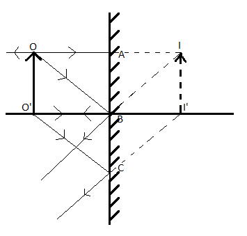
The attached figure shows the formation of image (II') of an extended object (OO') by a plane mirror.
Result
Image formation of extended object by plane mirror

To find out the position of the image formed by a plane mirror after reflection, take a plane mirror MM. Now place an extended object AB of size h on the left side of the mirror at a distance u.
An incident ray of light AP from the point A of the object AB falls normally on the mirror at point P, and is thus reflected back in the same path, along PA. The second ray of light AO strikes the mirror at point O and gets reflected along the path OC.
Now the reflected rays PA and OC are diverging rays and therefore cannot meet each other actually in front of the mirror. So we extend the reflected rays PA and OC backwards behind the mirror by dotted lines. On extending backward these rays appear to meet at point A at a distance v. So A is the virtual image of point A of the object AB.
In the same manner the virtual image B will be formed behind the mirror from the incident rays BO and BE falling on the mirror from point B of the object. To get complete image of object AB join the points A and B by a dotted line. On joining the points A and B we find that the image formed by a plane mirror is virtual, erect and of the same size as that of object.
Also on measuring the distance of object u and the distance of image v, it is found that the image is formed at the same distance behind the plane mirror as the object is in front of the mirror.
Following are the characteristics of an image formed by a plane mirror:
The image formed by a plane mirror is always virtual in nature.
It is erect.
It is of the same size as the object.
It is formed at the same distance behind the mirror as the object is in front of the mirror.
Law
Verify the law of reflection

Aim : To verify the law of reflection
Procedure:
Procedure:
1) Take a drawing board and fix a white paper on it with the help of clamps.
2) Draw a straight line AB at the centre of the paper and also a normal (ON) to AB at point 'O'.
3) Draw a straight line PQ making certain angle (Angle i) with ON.
4) Fix two pins at the points P and Q on the paper vertically.
5) Observe the image P' of the pin 'P' and 'Q' of the pin 'Q' in the mirror kept along the line AB.
6) Fix two more pins R and S such that they are in the same line as that of P' and Q'. Join RjS and 'O'.
7) Measure the angle between RS and ON (angle of reflection).
8) You will find that Angle of incidence = Angle of reflection
9) Repeat the experiment with different angles of incidence and measure the corresponding angles of reflection.
10) In all cases you will observe Angle of incidence = Angle of reflection
11) Hence 1st law of reflection is verified.
Example
Verification of laws of reflection
Laws of verification can be experimentally verified by drawing the trace of a ray of light before and after reflection. This can be done by passing light through a small hole in a dark room or using two thin objects (like needles/pins) to trace a straight line and observe its reflection.
 |
| BookMarks |
Page 12 Page 13 Page 14 Page 15 Page 16 Page 17 Page 18 Page 19 Page 20 Page 21
Page 22 Page 23 Page 24
0 Comments
Post a Comment